|
Click Up back to Electronic page
Symbol of
Resistance 
Resistors restrict the flow of
electric current, for example a resistor is placed in
series with a light-emitting diode (LED) to limit the
current passing through the LED. |
|
Resistor
values - the resistor color code
The Resistor
Color Code |
| Color |
Number |
| Black |
0 |
| Brown |
1 |
| Red |
2 |
| Orange |
3 |
| Yellow |
4 |
| Green |
5 |
| Blue |
6 |
| Violet |
7 |
| Grey |
8 |
| White |
9 |
Resistance is measured in ohms, the symbol for ohm is an
omega Ω.
1 Ω is quite small so resistor values are often given in kΩ and MΩ.
1 kΩ = 1000 Ω 1 MΩ = 1000000 Ω.
Resistor values are normally shown using colored bands.
Each color represents a number as shown in the table.
Most resistors have 4 bands:
 |
The first band
gives the first digit.
 |
The second band
gives the second digit.
 |
The third band
indicates the number of zeros.
| | |
This resistor has red (2), violet (7), yellow (4 zeros)
and gold bands.
So its value is 270000 Ω = 270 kΩ.
On circuit diagrams the Ω is usually omitted and the value is written
270K.
|
|
Small value
resistors (less than 10 ohm)
The standard color code cannot show values of less
than 10Ω. To show these small values two special colors are
used for the third band: gold
which means × 0.1 and silver
which means × 0.01. The first and second bands represent the
digits as normal.
For example:
red, violet,
gold bands represent
27 × 0.1 = 2.7 Ω
green, blue,
silver bands represent
56 × 0.01 = 0.56 Ω |
|
Tolerance of
resistors (fourth band of color code)
The tolerance of a resistor is shown by the fourth
band of the color code. Tolerance is the precision of
the resistor and it is given as a percentage. For example a 390Ω
resistor with a tolerance of ±10% will have a value within 10% of
390Ω, between 390 - 39 = 351Ω and 390 + 39 = 429Ω
(39 is 10% of 390).
A special color code is used for the fourth
band tolerance:
silver ±10%, gold
±5%, red
±2%, brown ±1%.
If no fourth band is shown the tolerance is ±20%. |
|
Resistor
shorthand
Resistor values are often written
on circuit diagrams using a code system which avoids using a
decimal point because it is easy to miss the small dot. Instead
the letters R, K and M are used in place of the decimal point. To
read the code: replace the letter with a decimal point, then
multiply the value by 1000 if the letter was K, or 1000000 if the
letter was M. The letter R means multiply by 1.
For example:
560R means 560 Ω
2K7 means 2.7 kΩ = 2700 Ω
39K means 39 kΩ
1M0 means 1.0 MΩ = 1000 kΩ
|
|
Resistors connected in
Series
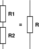
When resistors are connected in series
their combined resistance is equal to the individual
resistances added together. For example if resistors R1
and R2 are connected in series their combined
resistance, R, is given by:
Combined resistance in series:
R = R1 + R2
This can be extended for more
resistors: R = R1 + R2 + R3 + R4 + ...
Note that the combined
resistance in series will always be greater
than any of the individual resistances. |

|
|
Resistors connected in
Parallel
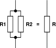
When resistors are connected in
parallel their combined resistance is less than any of
the individual resistances. There is a special equation
for the combined resistance of two resistors R1
and R2:
Combined
resistance of
two resistors in parallel: |
R
= |
R1
× R2 |
| R1
+ R2 |

For more than two resistors connected
in parallel a more difficult equation must be used. This
adds up the reciprocal ("one over") of
each resistance to give the reciprocal of the
combined resistance, R:
| 1 |
= |
1 |
+ |
1 |
+ |
1 |
+
... |
| R |
R1 |
R2 |
R3 |
The simpler equation for two
resistors in parallel is much easier to use!
Note that the combined
resistance in parallel will always be less
than any of the individual resistances. |
|
|
 |


 |