|
Click Up back to Electronic page
|
Transistor
circuit symbols
Transistors amplify current,
for example they can be used to amplify the small
output current from a logic chip so that it can
operate a lamp, relay or other high current
device. In many circuits a resistor is used to
convert the changing current to a changing
voltage, so the transistor is being used to amplify
voltage.
A transistor may be used as a switch
(either fully on with maximum current, or fully
off with no current) and as an amplifier
(always partly on).
The amount of current
amplification is called the current gain,
symbol hFE. |

|
|
|
Types Of
Transistors
There are two types of standard transistors,
NPN and PNP, with different circuit symbols. The letters refer
to the layers of semiconductor material used to make the
transistor. Most transistors used today are NPN because this
is the easiest type to make from silicon. If you are new to
electronics it is best to start by learning how to use NPN
transistors. |
Connecting
|
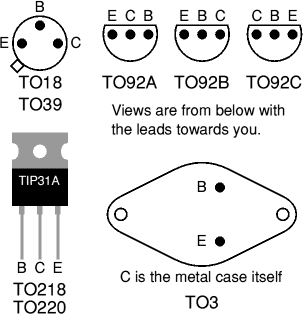
Transistors have three leads
which must be connected the correct way round.
Please take care with this because a wrongly
connected transistor may be damaged instantly when
you switch on.
If you are lucky the orientation
of the transistor will be clear from the PCB or
strip board layout diagram, otherwise you will
need to refer to a supplier's catalogue to
identify the leads.
The drawings on the right show
the leads for some of the most common case styles.
Please note that transistor lead
diagrams show the view from below with the leads
towards you. This is the opposite of IC (chip) pin
diagrams which show the view from above. |
 |
|
| Structure |
This
shows the type of transistor, NPN or PNP. The
polarities of the two types are different, so if
you are looking for a substitute it must be the
same type. |
| Case style |
There
is a diagram showing the leads for some of the
most common case styles in the Connecting section
above. This information is also available in
suppliers' catalogues. |
| IC
max. |
Maximum
collector current. |
| VCE
max. |
Maximum
voltage across the collector-emitter junction.
You can ignore this rating in low voltage
circuits. |
| hFE |
This
is the current gain (strictly the DC
current gain). The guaranteed minimum value is
given because the actual value varies from
transistor to transistor - even for those of the
same type! Note that current gain is just a number
so it has no units.
The gain is often quoted at a particular
collector current IC which is usually
in the middle of the transistor's range, for
example '100@20mA' means the gain is at least 100
at 20mA. Sometimes minimum and maximum values are
given. Since the gain is roughly constant for
various currents but it varies from transistor to
transistor this detail is only really of interest
to experts.
Why hFE? It is one of a whole
series of parameters for transistors, each with
their own symbol. There are too many to explain
here. |
| Ptot
max. |
Maximum
total power which can be developed in the
transistor, note that a heat sink will be
required to achieve the maximum rating. This
rating is important for transistors operating as
amplifiers, the power is roughly IC ×
VCE. For transistors operating as
switches the maximum collector current (IC
max.) is more important. |
| Category |
This
shows the typical use for the transistor, it is a
good starting point when looking for a substitute.
Catalogues may have separate tables for different
categories. |
| Possible
substitutes
|
These
are transistors with similar electrical properties
which will be suitable substitutes in most
circuits. However, they may have a different case
style so you will need to take care when placing
them on the circuit board. |
|
|
Darlington
pair
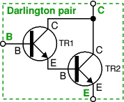
This is two transistors connected together so that the
amplified current from the first is amplified further by the second
transistor. This gives the Darlington pair a very high current gain such as
10000. Darlington pairs are sold as complete packages containing the two
transistors. They have three leads (B, C and E)
which are equivalent to the leads of a standard individual transistor.
You can make up your own Darlington pair from two
transistors.
For example:
 |
For TR1 use BC548B with hFE1
= 220.
 |
For TR2 use BC639 with hFE2
= 40. |
|

The overall gain of this pair is hFE1 × hFE2
= 220 × 40 = 8800.
The pair's maximum collector current IC(max) is the same as TR2. |
|
|
 |


 |