|
Click Up back to Electronic page
| Symbol
of Diode

Diodes allow electricity to flow in
only one direction. The arrow of the circuit symbol
shows the direction in which the current can flow.
Diodes are the electrical version of a valve and early
diodes were actually called valves. |
|
Reverse
Voltage
When a reverse voltage is applied
a perfect diode does not conduct, but all real diodes leak a
very tiny current of a few µA or less. This can be ignored in
most circuits because it will be very much smaller than the
current flowing in the forward direction. However, all diodes
have a maximum reverse voltage (usually 50V or more) and if this
is exceeded the diode will fail and pass a large current in the
reverse direction, this is called breakdown.
|
| Forward
Voltage Drop
Electricity uses up a little energy
pushing its way through the diode, rather like a person
pushing through a door with a spring. This means that
there is a small voltage across a conducting diode, it
is called the forward voltage drop and is about
0.7V for all normal diodes which are made from silicon.
The forward voltage drop of a diode is almost constant
whatever the current passing through the diode so they
have a very steep characteristic
(current-voltage graph).
|
| Connecting
and soldering
Diodes must be connected the correct way
round, the diagram may be labeled a or + for anode and k
or - for cathode (yes, it really is k, not c, for
cathode!). The cathode is marked by a line painted on
the body. Diodes are labeled with their code in small
print, you may need a magnifying glass to read this on
small signal diodes!
Small signal diodes can be damaged by
heat when soldering, but the risk is small unless you
are using a germanium diode (codes beginning OA...) in
which case you should use a heat sink clipped to the
lead between the joint and the diode body. A standard
crocodile clip can be used as a heat sink.
|
| Protection
diodes for relays
Signal diodes are also used with
relays to protect transistors and integrated circuits
from the brief high voltage produced when the relay coil
is switched off. The diagram shows how a protection
diode is connected across the relay coil, note that the
diode is connected 'backwards' so that it will normally
NOT conduct. Conduction only occurs when the relay coil
is switched off, at this moment current tries to
continue flowing through the coil and it is harmlessly
diverted through the diode. Without the diode no current
could flow and the coil would produce a damaging high
voltage 'spike' in its attempt to keep the current
flowing. |
| Rectifier
diodes (large current)
Rectifier diodes are used in power
supplies to convert alternating current (AC) to direct
current (DC), a process called rectification. They are
also used elsewhere in circuits where a large current
must pass through the diode.
All rectifier diodes are made from
silicon and therefore have a forward voltage drop of
0.7V. The table shows maximum current and maximum
reverse voltage for some popular rectifier diodes. The
1N4001 is suitable for most low voltage circuits with a
current of less than 1A. |
| Diode |
Maximum
Current |
Maximum
Reverse
Voltage |
| 1N4001 |
1A |
50V |
| 1N4002 |
1A |
100V |
| 1N4007 |
1A |
1000V |
| 1N5401 |
3A |
100V |
| 1N5408 |
3A |
1000V |
|
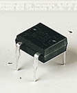
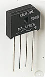
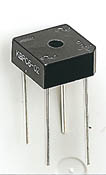
Bridge
rectifiers
| There are several
ways of connecting diodes to make a rectifier to
convert AC to DC. The bridge rectifier is one of
them and it is available in special packages
containing the four diodes required. Bridge
rectifiers are rated by their maximum current and
maximum reverse voltage. They have four leads or
terminals: the two DC outputs are labeled + and -,
the two AC inputs are labeled ~. |
 |
|
|
Various types of
Bridge Rectifiers
Note that some have a hole through their center for
attaching to a heat sink |
|
|
 |


 |