|
Click Up back to Circuit page
Light House
|
This project was designed
for a model lighthouse to flash a lamp in a simple
sequence: two flashes of 2s with a short gap of 1s,
followed by a longer gap of 5s before repeating the
sequence.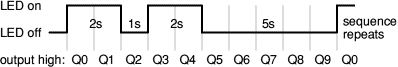 |
| The 555 timer
is connected as an astable to provide clock pulses for
the 4017 counter. The 4017 has ten outputs (Q0 to Q9)
and each one becomes high ('on') in turn as the clock
pulses are received. Outputs Q0, Q1, Q3 and Q4 are
combined with diodes to produce the flash sequence. A
transistor amplifies the current to power the lamp, or
LED if you prefer (a 470Ω LED resistor is included
on the strip board layout). The 1MΩ preset
controls the time period (T) of the 555 astable from
about 0.1s to 1.5s, for example set T = 1s.
For a different flash sequence connect
the diodes to combine different 4017 outputs (Q0-Q9). If
the full count from 0 to 9 is not required one of
outputs can be connected to the reset input (pin 15).
For example connecting Q8 (pin 9) to reset (pin 15)
reduces the long gap at the end of the sequence to 3s
(with T=1s). |
Parts Required
 |
resistors: 470, 2k2,
22k, 100k
|
capacitors: 0.1µF,
1µF 16V radial
|
diodes: 1N4148 ×4
|
transistor: BC108 (or
equivalent)
|
1M preset, horizontal
|
6V 60mA MES lamp
|
MES lamp holder
|
555 timer IC, such as
NE555
|
4017 counter IC
|
DIL sockets for ICs:
8-pin, 16-pin
|
on/off switch
|
battery clip
|
9V battery box for 6
AA cells
|
strip board: 19 rows
× 21 holes |
| | | | | | | | | | | | |
|
|
Strip
board Layout

|
|
Circuit
diagram
|
|
|
 |


 |